
CMC-1417AE Manual
The CMC−1417AE VGA Color Monitor originally shipped with a user guide that walked owners through setup, daily operation, and essential safety practices. It described which VGA adapters the display supported, showed how to attach the 15−pin D−sub cable, and detailed the front−panel controls used to switch the unit on and fine−tune brightness and contrast. The guide also covered basic diagnostics, including the monitor's built−in self−test, instructions for attaching or removing the tilt−and−swivel base, and notes on meeting FCC regulations. A full set of technical specifications, such as supported resolutions up to 640×480, electrical requirements (AC 100–240V), and signal parameters, was provided to help users configure the monitor correctly and service it when needed.
The original user guide for the CMC−1417AE VGA Color Monitor, a compact 14−inch analog CRT display, served as a complete, step−by−step reference for owners, covering everything from initial unboxing and safe installation to everyday operation, troubleshooting, and technical configuration. It began with a clear statement of quality assurance and a strong emphasis on safety, reminding users that the power supply cord acts as the main disconnect device and must be unplugged before any servicing. Prominent caution and warning sections highlighted the risk of electric shock, fire hazards from exposing the unit to rain or moisture, and the importance of qualified service personnel only. A dedicated FCC radio frequency interference statement confirmed the monitor had been tested to Class B digital device limits and provided practical tips for minimizing interference, such as reorienting the receiving antenna, increasing separation from other equipment, or consulting a dealer or technician.
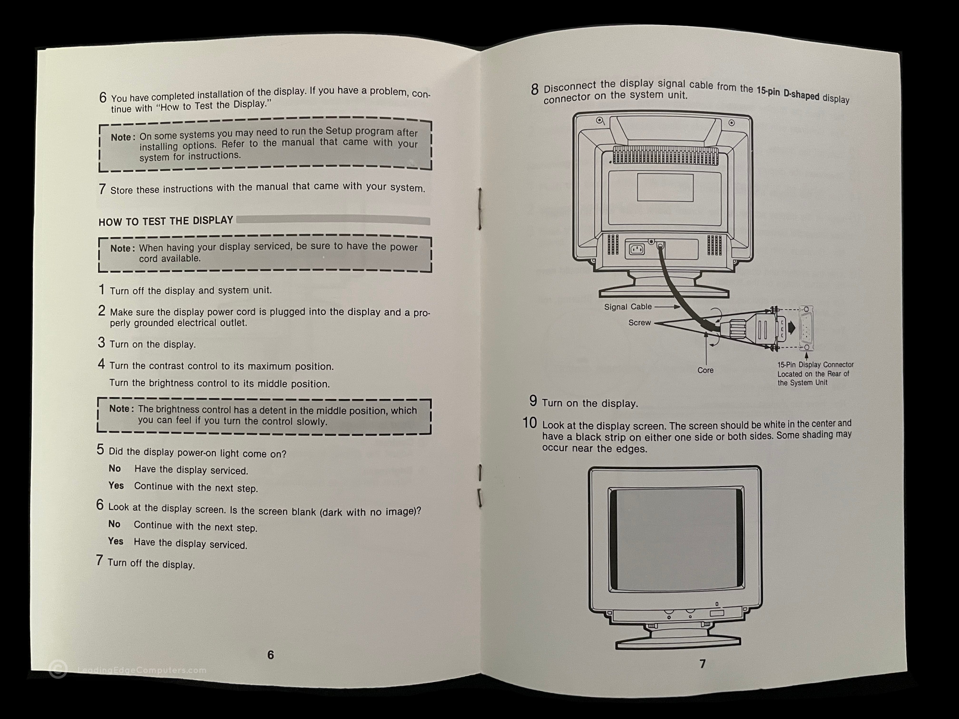
Installation instructions were straightforward and illustrated with diagrams. After turning off the system unit and all peripherals, users were guided to connect the 15−pin D−sub signal cable to the matching VGA connector on the computer, noting that the D−shaped shell ensures it can only plug in one way, then securely tighten the thumbscrews. Power connection followed only after verifying the wall outlet matched the monitor's universal AC 100–240V 50/60 Hz rating; the guide explicitly warned against using any other voltage or direct current and against ever removing the back cover. Front−panel controls were clearly labeled and illustrated: the Power switch with adjacent Power−On indicator light, contrast knob, and brightness knob, noted to have a tactile detent at the midpoint for easy reference.
A built−in self−test feature provided quick verification of basic operation. After disconnecting the signal cable, powering on the monitor produced a full white screen with black borders on one or both sides. The guide then walked users through a complete diagnostic flowchart: checking that the power−on light illuminated, confirming the screen was not blank when connected, verifying a stable image during the self−test pattern, and finally confirming normal video output once reconnected to the system unit. If issues persisted such as blank screen, jitter, rolling, shifting, out−of−focus text, or unresponsive brightness / contrast controls, the guide directed users to have either the monitor or the system unit serviced.
Additional practical sections covered mechanical adjustments and maintenance. Detailed illustrated steps explained how to remove or install the optional tilt/swivel stand: turning the monitor upside−down, pushing the base forward, squeezing the latches to release it, then aligning and locking the stand back into the bottom slots until it clicked securely. Every day use cautions reinforced best practices, positioning the screen just below eye level to reduce fatigue, ensuring proper ventilation, keeping the unit away from strong magnetic fields or heavy objects on the power cord, and avoiding damp, dusty, or high−traffic environments.
The guide concluded with complete technical reference material. A pin−assignment table detailed the 15−pin VGA connector signals and a specifications table listed:
- CRT: 0.39 mm dot/stripe pitch, P22 or equivalent phosphor, 13V non−glare/glare faceplate, 57% light transmission, tinted.
- Video: Analog RGB input, 240×180 mm display area.
- Horizontal: 31.5 kHz, max. 640 dots resolution.
- Vertical: 60/70 Hz, 350/400/480 lines resolution.
- Sync polarity: Specific positive/negative combinations for each line count.
- Power: Universal 100‐240 VAC 50/60 Hz.
These details enabled precise system configuration and confirmed the monitor's compatibility with standard VGA adapters, including IBM PS/2 cards, its ability to display 640×480 resolution with unlimited colors, and its self−test white−pattern capability. In short, the manual transformed what could have been a simple hookup guide into a thorough, safety−focused, and technically complete resource that empowered users to install, operate, diagnose, and maintain their CMC−1417AE monitor with confidence.
See below for a downloadable high‐quality scan PDF.
 LeadingEdge
Downloads
CMC-1417AE Manual PDF
Downloadable PDF:
Downloads require CAPTCHA verification to prevent abuse and protect bandwidth.
Download available after verification.
